VOR Navigation
Part I
The widespread introduction of VORs began in the early 1950s and 50 years later it remains the primary navigation system in the overwhelming majority of aircraft.
If you jumped to this point of the website without proceeding through the earlier sections, I strongly recommend that you return to the Air Navigation section and review the sections on VFR Sectional Charts, IFR enroute low altitude charts, and the basics of plotting a course. Further, you should go to the NDB Approaches/Approach Plates section and read the basics of Instrument Approach Plates, now called Terminal Procedures.
The basic principle of operation of the VOR is very simple: the VOR facility transmits two signals at the same time. One signal is constant in all directions, while the other is rotated about the station. The airborne equipment receives both signals, looks (electronically) at the difference between the two signals, and interprets the result as a radial from the station.
The GPS, Global Positioning System, is making inroads onto the navigation scene and offers a flexibility unavailable with either NDB or VOR systems. However, it is supplementing these systems, not replacing them.
The RMI indicator used in the NDB navigation exercises is as close to a "hands-off" indicator as you will find. In an aircraft the RMI compass card must initially be aligned with the compass before a flight begins and then rechecked every fifteen minutes or so, and that's it.
With VOR, however, course information must be manually entered into the indicator. The VOR indicator below shows an aircraft heading toward, "TO," the Omni station.
NOTE this very important fact, with more info farther down. The radial signals of a VOR always point away from the station. The indicator below shows 345°, but since we are heading toward the VOR, see arrow D, we are actually on the reciprocal radial, or the 165° radial. This aircraft is south of the station. This will become more clear in a moment.
See the text for details on the four components of the VOR Indicator.
The digital indicator is a separate gauge used on the Nav Trainer Panel.
The VOR display has four elements:
- A Rotating Course Card, calibrated from 0 to 360°, which indicates the VOR bearing chosen as the reference to fly TO or FROM. Here, the 345° radial has been set into the display. This VOR gauge also digitally displays the VOR bearing, which simplifies setting the desired navigation track.
- The Omni Bearing Selector, or OBS knob, used to manually rotate the course card.
- The CDI, or Course Deviation Indicator. This needle swings left or right indicating the direction to turn to return to course. When the needle is to the left, turn left and when the needle is to the right, turn right, When centered, the aircraft is on course. Each dot in the arc under the needle represents a 2° deviation from the desired course. This needle is more-frequently called the left-right needle, with the CDI term quickly forgotten after taking the FAA written exams. Here, the pilot is doing well, and is dead-on course—or maybe lazy and with the autopilot activated in the "NAV" mode.
- The TO-FROM indicator. This arrow will point up, or towards the nose of the aircraft, when flying TO the VOR station. The arrow reverses direction, points downward, when flying away FROM the VOR station. A red flag replaces these TO-FROM arrows when the VOR is beyond reception range, has not been properly tuned in, or the VOR receiver is turned off. Similarly, the flag appears if the VOR station itself is inoperative, or down for maintenance. Here, the aircraft is flying TO the station.
Radials, Radials, Radials
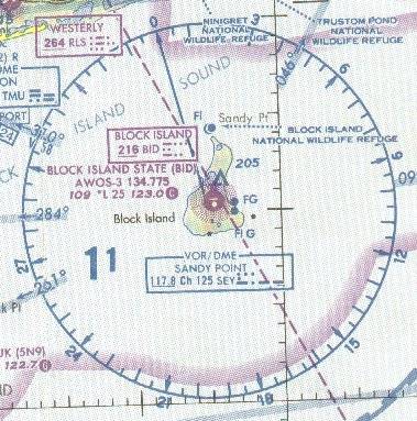
In the Sandy Point VOR to the left, note first that the arrow on the 0° radial points away from the center of the compass rose. You'll remember that this radial points to the west of true north because of the west magnetic variation. North on a VOR is Magnetic North. So, if you overflew this VOR on the 0° radial, you would be flying away from the VOR.
Similarly, note the arrows by the 30°, 60°, 90° marks and the rest of the way around the compass rose. They all point away from the station. Radials are always away from the station.
There is only one line on the chart for each numbered radial for a particular VOR station. Whether you are flying it outbound or inbound, or crossing it, a radial is always in the same place.
The only possible complication lies in the reciprocity of the numbers. Whenever you are proceeding outbound, your magnetic course (and heading when there is no wind) will be the same number as the radial. Turn around and fly inbound you must mentally reverse the numbers and physically reverse the OBS setting so that your course is now the reciprocal of the radial. But the radial you are flying on hasn't changed.
Some examples will cement this in your mind.
- The aircraft isn't on the 345° radial because that radial extends from the Omni to the northwest as shown by the arrow.
- The aircraft is actually on the reciprocal radial, the radial pointing towards the plane. That reciprocal radial is 165°, away from the station like all radials.
- If the 165° radial were set into the VOR, the FROM flag would properly show, because the aircraft is away from the Omni on that radial.
- Here is the important point. If the OBS is rotated until the needle centers and the FROM flag shows, it will always show the correct radial from the Omni that the aircraft is on regardless of the aircraft heading.
- To eliminate the confusion of location relative to an Omni, the magnetic course of the aircraft and the radial setting on the VOR should be the same.
- Presumably the aircraft is flying in the desired course direction, so its heading will be approximately the same as the VOR setting, i.e., the magnetic course. The heading may differ slightly from the VOR because of the correction needed to correct for wind drift.
- Thus, with the OBS set to 345° the left-right needle shows the aircraft on course and the TO flag is showing, pointing up, toward the station ahead.
Experiment with this on your FS98 or FS2K to see the effects of the OBS setting on the TO-FROM flag. Select any Omni, position the aircraft to be flying TO it, then rotate the OBS so that its reading centers the needle and the TO flag appears.
Next, rotate the OBS to the reciprocal of the course. The needle will again center, but the FROM flag will appear.
A one-line recap: to know whether you are flying TO or FROM an Omni, the OBS setting must be approximately the same as the aircraft heading.
Where am I?
Same example as before. The aircraft is south of the Omni, on the 165° radial. It is flying northwest. Observe the DG. The aircraft is heading 345° as desired. But the OBS was improperly set to 165° and the VOR is falsely informing the pilot, with a nicely centered needle, that he/she is flying away FROM the Omni. The aircraft, of course, is flying TO the Omni.
Hate to beat a dead horse, but again, the TO-FROM confusion disappears if the aircraft heading and the OBS setting are approximately the same which they weren't here. Pay attention to this and you will stay out of trouble.
This sort of error usually happens when the pilot rotates the OBS, watching only for a centered needle, not also paying attention that the setting should approximate the magnetic course, or aircraft heading.
Wandering off course?
This aircraft is 4° off course. Each dot of the arc under the needle is a 2° deviation from the desired course. Don't confuse heading, the direction of the aircraft's nose, with course, the desired track along the ground. Only with no wind will heading and course be the same.
"The needle is centered, my flying is perfect"
![]() Nice thought, but not necessarily. The VOR system operates in the VHF frequency band, from 108.0 to 117.95 MHz. Reception of VHF signals is a line-of-sight situation. Nominally, you must be 1000 ft AGL to pick up an Omni within its maximum low-altitude service range.
Nice thought, but not necessarily. The VOR system operates in the VHF frequency band, from 108.0 to 117.95 MHz. Reception of VHF signals is a line-of-sight situation. Nominally, you must be 1000 ft AGL to pick up an Omni within its maximum low-altitude service range.
The VOR indicator is smart enough to know when a usable signal has not been received and displays an "OFF" flag, a red and white barber-pole striped flag in the gauge in the illustration to the left. So when you are flying to or from an Omni station and you're quite content at how stable the CDI needle has been, it's worth taking another glance at the gauge to see if the OFF flag is staring back at you.
The OFF flag also displays if the Nav receiver is tuned to the wrong frequency or, blush, if it's properly tuned but you neglected to turn on the power switch. If you're taking your check ride with an FAA examiner for a real license, that oversight is likely to get you a quick return to terra firma. And, there's also the possibility of a popped circuit breaker interrupting power to the Nav receiver, a connector jiggled loose, etc.
VOR Range
Ah, the oft asked and seldom answered question: how far away can I pick up a reliable signal from the Omni and what altitude need I be at? The FAA neatly skirts the answer by classifying Omnis by an altitude code, with the ranges vs. altitudes as shown in the table below.
| VOR Class |
Range nm |
within Altitude feet |
| Terminal (T) | 25 | 1000 – 12,000 |
| Low Altitude (L) | 40 | 1000 – 18,000 |
| High Altitude (H) |
40 100 130 |
1000 – 14,500 14,500 – 60,000, 18,000 – 45,000 |
These ranges assume, please contain your laughter, that terrain plays no part in VOR ranges of reception. But terrain, of course, can greatly impact the reliable range of an Omni.
Consider the Bangor VOR, BGR, at Bangor (Maine) Int'l. Airport. Here are the comments in the Airport/Facility Directory:
"VOR unusable 342°—063° below 2500 ft."
Pretty significant terrain impact, wouldn't you say? So think of the FAA data in the table as a starting point that may be modified by terrain.
Checking VOR accuracy
The VOR is the most common navigation instrument presently on aircraft panels. We rely on it to accurately track VOR radials, whether flying between Omni stations, or locating intersections, or arriving and departing from airports. We accept at face value that what it displays is accurate. Well, on FS98 and FS2000 it is always accurate. But in the real world, not only can the gauge be wrong, but the FAA requires that a pilot check the VOR for accuracy within 30 days of an IFR flight. Even if a pilot never flys IFR, it is prudent to regularly check the VOR for accuracy.
One acceptable way to formally check VOR accuracy is with a VOR Test Facility, more commonly called a VOT. A VOT is a low-power Omni station located on many of the mid-to-large size airports. A VOT differs from a standard Omni in that it transmits only a single radial, the 360° radial.
To calibrate a VOR, the pilot tunes in the VOT frequency while on the ground (in rare instances this check is performed in the air). Refer to the back of the Airport/Facility Directory for frequencies and whether it is a ground check (G) or an airborne check (A). See the Connecticut illustration below.
| Facility (Arpt Name) | Freq. | Type VOT | Remarks |
| Bradley Int'l | 111.4 | G | |
| Bridgeport (Sikorsky Mem) | 109.25 | G | |
| Groton (Groton–New London) | 110.25 | G | |
| Hartford (Hartford–Brainard) | 108.2 | A | 3 nm Radius 1200–5000 ft. |
Next, rotate the OBS until the to-from needle centers. Read the number from the Omni Bearing Indicator ring or digital display. To be legal, the gauge must be within 4° of either 180° with the TO flag showing or of 0° with the FROM flag showing.
Make note in the illustration above that the VOT at Bradley Int'l. airport is on 111.4 MHz. That information is important later while performing one of the VOR approach practice flights.
It's time to fly—All flights will be on the New York Sectional Chart.
Site best viewed at 600 × 800 resolution or higher.
© 1999 – 2008, Charles Wood.