On the Beam
He shook his head smiling wistfully and stared at his coffee. So much has changed, he thought. Student pilots don't even get sent to the hangar for a bucket of prop wash anymore.
The old-timer's mind drifted back to the '40s, when he was a young airline pilot. Radio navigation was so different then. "A" and "N," which side on this leg?
While early flashing beacons were economical and a great aid for night-time navigation in clear weather, they were of no value in overcast conditions, or during the day when they werent even turned on. And they were sometimes difficult to locate in the distracting light of urban sprawl. These handicaps hastened the development of the LF navigation system.
Radio beacons in the 190 to 535 kHz radio band had formed the earliest LF navigation system. These powerful, 1500-watt beacons were spaced about 200 miles apart and defined electronic airways. A pilot flew for 100 miles guided by the beacon behind him and then tuned in the beacon ahead for the next 100 miles. The beam width was about 3° so it was important that the pilot promptly tune in the station in front. At 100 miles and a 3° beam width, the aircraft was "on course" if it were within ±2.6 miles of the airway centerline.
The beacons transmitted two Morse-code signals: the letter "A," • – , and its opposite, the letter "N," – • . When the aircraft was centered on the airway, or electrical beam, these two opposite Morse-code signals merged into a steady, monotonous, hypnotizing tone. Broadcast of the beacon's Morse-code identification interrupted these tones twice a minute.
If the aircraft drifted off course to one side, the Morse code for the letter "A" could be faintly heard. The greater the drift, the stronger the "A" Morse code signal. Straying to the opposite side produced the "N" Morse code signal.
| The four-course radio range. One antenna's figure-eight pattern transmits Morse-code "A," and the other antenna's figure-eight pattern transmits Morse-code "N." The "On-Course" signal develops where the two figure eight-patterns overlap (shaded) and the two Morse-code signals interleave to provide a constant tone. |
The illustration shows the beacon's two figure-eight transmission patterns. Where they overlapped was "the beam." One can see that technically, beams weren't actually transmitted. But the term "on the beam" was so entrenched with pilots that it became common usage.
Because of the dual loop-antenna system used, each beacon defined four airways, and hence this system was named the four-course radio range. With the letter "A" to the aircraft's left heading towards the beacon on two of the courses, and to its right on the other two courses complicated navigation. Worse, the letters didn't stay put. When the aircraft passed over the beacon, from inbound to outbound, the letters switched from one side of the airway to the other.
Station passage was marked by a "cone of silence," where the aural tone briefly disappeared as the aircraft flew directly overhead.
When possible, radio-range stations were located near an airport, and situated so that one of the four beams lined up with the principal runway, "thus facilitating radio approach landings under conditions of low visibility."
While not pin-point accurate, the radio-range system was a great leap forward over simple dead-reckoning navigation or flashing beacons.
Pilots became very skilled at flying the four-course radio range. As mentioned, a station identified itself every half-minute. It first broadcast its call letters in the "N" quadrant and then in the "A" quadrant. Pilots could hear both broadcasts. If the two signals were equal volume, a pilot knew that he was "on course." But, for example, if the call sign from the "N" side was louder, he knew that his aircraft was off center and he should adjust his heading towards the other side of the airway. Many pilots found it easier to stay on course by monitoring the call-sign transmissions than by listening to the steady tone.
In fact, a pilot was encouraged to fly off-center from a radio-range beam, to fly the right-hand edge of the beam. This reduced the possibility of encountering an aircraft coming from the opposite direction, particularly when flying IFR in the days before ATC assigned altitudes.
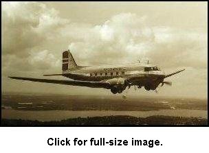
Eighteen months after the four-course radio range system was launched it was deemed essential to aviation. This navigation system revolutionized airline transportation as much as the introduction of the DC-3. For the first time, scheduled air service meant just that. Only infrequently did poor weather or low ceilings or limited visibilities cancel a flight.
When flying through mountain passes in IFR weather or on a dark night, the pilots paid close attention to the tones in their headphones. Palms became moist in the cockpit when static from electrical storms interfered with the reception of those crucial signals—or when beacon signals bounced off the canyon walls and gave false information.
Radio Direction Finding
The LF radio-range system had two principal drawbacks: it provided no information on the aircraft's position nor whether it was flying to or from a beacon. If a pilot were flying along a known airway he could extrapolate the to/from situation with a drift off course slightly to pickup the "A" or "N," then deduce from the charts whether the beacon was in front or behind him.
A number of maneuvers were available to a pilot to eliminate the ambiguity of which direction the beacon was relative to his heading, or to determine which quadrant of the radio range he was within, or identify which beam of the range he was intercepting. These maneuvers had names such as the 90° turn method and the parallel method. Useful as they were, they each required a significant deviation from the aircraft's intended course, sometimes even a 180° turn away from the station.
The installation of marker-beacons every 20 to 30 miles along the airway partially informed the pilot of his position. Each beacon transmitted a distinct identification signal and so on passage a pilot could mark his progress to the next four-course station.
The old-timer shook his head again, his thoughts deep into the past.
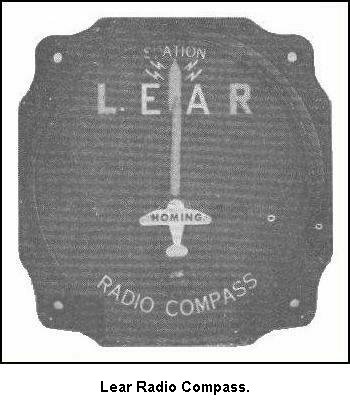
The Radio Compass was the first glimmer of hope in determining bearings to a radio station, of filling the information void of the four course radio range. It added a fixed loop antenna and visual indicator to the receiver system. With this system, as long as the aircraft was headed directly toward a radio station the needle of the indicator remained centered; headings to the right or left of the station resulted in a corresponding deflection of the needle.
The radio compass was chiefly used as a "homing" device, and bearings of radio stations off the line of flight could be obtained only by turning the aircraft toward the station and noting the magnetic compass heading when the needle was centered.
Replacing the fixed loop antenna with a rotatable loop eliminated this cumbersome maneuver. This system was called a Radio Direction Finder. With the rotatable loop, bearings could now be obtained without turning the airplane itself. The pilot or navigator would rotate the loop, usually mounted on the fuselage below the cockpit, to the position of minimum signal strength, or "null." The bearing to the radio station was then read from a graduated, mechanical dial.
By repeating this procedure with a second beacon an aircraft's position could be determined by triangulation after locating the two stations on the flight chart.
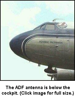
![]() The Automatic Direction Finder, a marvelous invention, followed the RDF. Finally, a self-contained apparatus for aircraft navigation was available. Gone were rotatable loop antennas and guess-work readings from mechanical azimuth dials. The ADF indicator needle always points directly towards the beacon, which now could be a Non Directional Beacon—NDB. Rick Covington's photograph of a Piedmont DC-3 shows the ADF antenna mounted below the cockpit.
The Automatic Direction Finder, a marvelous invention, followed the RDF. Finally, a self-contained apparatus for aircraft navigation was available. Gone were rotatable loop antennas and guess-work readings from mechanical azimuth dials. The ADF indicator needle always points directly towards the beacon, which now could be a Non Directional Beacon—NDB. Rick Covington's photograph of a Piedmont DC-3 shows the ADF antenna mounted below the cockpit.
The NDB provides good, basic navigation capabilities. An aircraft can follow the ADF needle to home to the station, although this is poor navigation practice—see later. The aircraft can track a specific NDB radio radial—electronic highway—to fly a specific course to or from the NDB station. The pilot can use two crossing radials to triangulate a position for a navigational fix. With a timer, its even possible to determine time and/or distance to and/or from an NDB station.
In addition, and probably the most prominent use of the NDB, it can provide an instrument approach procedure for landing. A pilot could now locate a runway without actually seeing it, to descend through overcast and/or low visibility conditions and land the aircraft by reference to the ADF indicator, the compass and the clock or a timer.
Yep, mused the old-timer, as he refilled his coffee, the ADF sure simplified navigation.
Click on the ADF Basics button to see what the old-timer meant.
Site best viewed at 600 × 800 resolution or higher.
© 1999 – 2008, Charles Wood.